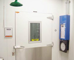
Redundant Refrigeration and Control Systems for Critical Material Storage

Valuable products, testing, or research often require the utmost in system reliability. This type of storage reliability and serviceability can only be achieved through the installation of a truly redundant system. There is often confusion that simply specifying a backup compressor means "redundancy" and that this is the only critical component.
If, for example, a compressor suffers a "burnout" failure at some point during operation, the entire refrigeration system will be compromised. Simply starting a backup compressor to operate in its place will quickly lead to a secondary failure. For this reason, the BioCold system is based upon two entirely separate refrigeration systems, including both high and low sides (condensing and evaporator unit) and the proper duplication of controls and power supplies to operate them. The following is BioCold's scenario for low temperature freezers. Much of the same logic may be used for cold rooms, warm rooms, and stability rooms that require redundant systems for critical storage and stability testing of material.
Method of operation: each compressor/condenser unit will have an independent power supply that will not originate nor circuit from the control console. The control console will normally be mounted on the face of the room and have two (2) circuits of 460/3-Phase or 208/3-Phase (select) and one circuit of 115 volts, 20 amps. These circuits are for the two (or more) evaporators, controls, lights, and condensate drain line heaters. There will be no electrical interlock circuit from the control console to the remote compressor/condensers. Each condensing unit will pump down on temperature control and the redundant (backup) system will be on pump down standby.
During a high temperature alarm event, the primary system that is online at the time of the event will be locked out and the redundant (backup) system will start and run immediately. The console will identify and alarm a system failure. This failed system will continue to be locked out and alarming even when the backup system brings the freezer, or other system back to temperature, until it is manually at rest.
During a defrost cycle of the primary system, the backup system will anticipate and start ahead of defrost time to "get up to speed" and run continually without cycling for temperature control before, during, and after (for adjustable periods) primary defrost. Upon defrost completion, both systems will operate for a predetermined amount of time, until the primary system has returned to full capacity to control the temperature inside the freezer. This "lead" and "lag" system enables a greatly reduced or eliminated temperature rise during normal defrost. At any time, at the control console, any system may be switched online to become the primary system with the other as backup. At any time, systems may be switched online to run together for additional capacity pull-down for large loads, checking pressure, service, or operation. Systems will alternately go online, at predetermined intervals ¾ i.e., every three days, in order to provide equal run/wear time and proper oil movement. This scenario also enables a regular selftest and failure discovery to avoid a failed backup. Time intervals are userselectable, as are all parameters.
The control console will have two independent microprocessor-based temperature controls with dual display of temperature set-point and actual temperature in 0.1°C increments. Controls are menu-driven with adjustable dead-bands and high/low temperature safety alarms with remote alarm dry contacts.
Temperature controls will be NIST traceable and certified. Temperature controller and recorder sensors will be 3-wire platinum 100 ohm precision band 5 RTD 3850 alpha. All solenoid valves are "rapid cycle type," switched through solid state SSR relays from the microprocessor-based temperature controllers.